Miscellaneous

FIRESTA-Bridge Reconstruction

Bridge Reconstruction

USPA NEWS - The objective of the reconstruction of the bridge was to improve its technical condition and to secure the required track speed of 160 km/h. The load-bearing structure showed technical problems - the design of the load-bearing structure itself was inappropriate (the structure was a prototype when it was built). In the original state, each of the railroads led over the relief arm of the Dyje (Thaya) river via a bridge consisting of three consecutive plain sections with spans of 24.0 + 63.0 + 24.0 m. The outer section was made up of a beam structure with solid-panel main supports and a lower orthotropic deck. The middle section was formed by a Langer Beam. The lower structure was composed of supports and two pillars. The deep foundations - supports and pillars - were made of reinforced concrete. The deck of the bridge was a so-called R65 and was attached directly to the bridge plating.
During the reconstruction, a new supporting structure of the bridge was built. The contractors decided to use a steel structure with flat-bottomed beams of closed cross-section, reinforced by a non-rigid arc with crossed rods. It was a simple section, a so-called “meshed arch“. In the central part of the main support beams, a ballast of dried silica sand was placed to rectify the tension of the rods. The supporting structure is mounted on unidirectional movable steel calotte bearings with guide bearings centred on both supports. The longitudinal effects are captured in the bridge dilatation control system. The uniqueness of the supporting structure lies in the slant of the bridge structure (41°), the arched rods and the use of a lever-controlled bridge dilation system used for slanted mounting ““ such a solution was used in the Czech Republic for the first time. The supporting structure was insulated with sprayed insulation.
The structure consists of 21 operational sets and building objects with the main one being the bridge structure. The construction included facilities for security devices, securing the rail-switch, superstructure and substructure, cable and traction lines. Main parameters of the bridge: “¢ Size of the supporting structure: 97.500 m “¢ Bridge length: 129.90 m “¢ Angle of the bridge: 41o “¢ Construction height of the supporting structure of the bridge: 15.64 m at mid-span “¢ Width of the bridge: 16.90 m (1 supporting steel structure 8.15 m) Building progress: In order to allow for the construction with one railroad closed and one open and at the same time accommodate the double-track traffic from the Austrian side, a railroad switch was installed before the construction began. The railroad switch was situated about 500 m from the bridge in the direction of Austria. This allowed for two-track traffic on the Austrian side and single-track on the bridge. foundation pits; the bracing was performed using soldier beams from the I girder and filled with planks. This was followed by grounding anchors and concreting of the 48 units for each support according to the requirements of the project documentation.
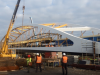
Construction of the new structure was carried out on an assembly platform behind the Austrian support. Individual parts of the main support beams and the bridge deck were brought in. Next, longitudinal insertion was carried out into the opening, followed by the construction of the arc and its reinforcement. A separate chapter in the assembly of the steel structure consisted of the assembly and tensioning of the rods. Each rod was fitted with two strain gauges before the suspension, the arc and beams were also fitted with strain gauges. The strain was monitored the entire time that the rods were being fitted. A separate lengthy report was needed for the process of fitting the rods. During the assembly of the rods, the main beams were filled with permanent ballast from dried silica sand - about 150 tons in one structure. After installing the steel bearing structure 1 on the bearings and finishing the insulation, elements of the controlled dilatation bridge system were prepared. After installing the dilations and loading the bridge with a constant load (railway superstructure) was system activated. Diagram of SŘDM (controlled bridge dilation system) on the bridge After that, a static loading test was carried out on the 1st track and traffic on the 1st track was introduced at a speed of 50 km/h.
After the slide track was dismantled, dynamic load tests and braking tests were carried out by two Taurus locomotives and the required amount of fully loaded wagons. For dynamic load tests, those amounted to nine wagons, and for the braking tests one wagon. Conclusion: Thanks to the efforts of all the parties involved, we have succeeded in finishing a project, which is unique on the Czech railway in several key points. The production and installation of the steel structure was one of the most demanding that Firesta has ever carried out.
Liability for this article lies with the author, who also holds the copyright. Editorial content from USPA may be quoted on other websites as long as the quote comprises no more than 5% of the entire text, is marked as such and the source is named (via hyperlink).